
Computer Simulation Facilitates Ninefold Improvement In Heat Exchanger Efficiency

Cal Gavin Ltd., Birmingham, UK
Contents
Computer simulation helped increase the efficiency of a heat exchanger by a factor of nine by showing that wire matrix inserts would overcome a flow distribution problem. The customer consulted Cal Gavin because an installed 324-tube exchanger was only providing a fraction of its theoretical performance. The subsequent simulation with computational fluid dynamics (CFD) software from Fluent Inc. (Lebanon, NH) showed that nearly 70% of the exchanger pressure drop was lost across the nozzles. The remainder was insufficient to evenly distribute the fluid through the tube bundle. Further analysis indicated adding inserts to increase the flow resistance of the bundle could solve the problem.
Heat exchanger analysis (back to top)
Cal Gavin's primary business is consulting on process improvements for handling mass and energy flow. Services provided by the firm include integrated plant reviews, design and simulation, CFD modeling, operability studies, troubleshooting, optimization, debottlenecking, team support. Cal Gavin specializes in fluid contacting dynamics for combined heat and mass transfer, correction of fluid, fractional crystallization, reaction engineering, flow regime control and fluid mixing and dispersing. The company sponsors a progressive program of fundamental research both in-house and in universities in the UK and numerous countries worldwide.
In the application described above engineers from a German chemical company contacted Cal Gavin with a problem which conventional approaches failed to resolve. The 700-mm-dia., 2,500-mm-long vertical exchanger had 200-mm nozzles on the tubeside. It was designed to operate with a tubeside flow of 90,757 kg/h at 69.5°C with the fluid density at 873 kg/m3 and viscosity of 1 cP. The heat exchanger was providing far less thermal duty than necessary for the application. The alternative solution to this problem would have been to replace the exchanger with a larger involving significant installation work.

Cal Gavin engineers recognized that, in theory, the heat exchanger should have been able to meet required duty and suspected a fluid flow distribution problem. While heat exchanger design typically focuses on surface area requirements the fluid flow within the tubes can be of equal importance. A shell-and-tube heat exchanger consists of a bundle of tubes through which one fluid flows whist the other fluid flows around the tubes. This accommodates a large surface area in a given volume. The target is obviously equal distribution of flow in each tube. Should most of the fluid flow through just a few tubes the majority of the installed surface area is wasted.
The next important consideration is fluid flow within individual tubes. Fluid flow dynamics through plain bore tubes do not provide ideal conditions for either heating or cooling. Frictional drag at the wall and viscous shear forces within the fluid create a velocity profile with maximum flow at the center of the tube and zero flow at the wall. Even where turbulent flow is fully established, a significant boundary layer still persists in both single and two phase flow regimes. The result is poor heat transfer through the boundary layer and the need for a much larger heat exchanger than would otherwise be the case.
Fluid flow conditions are typically assumed to be ideal because there is no simple way to make experimental measurements within an exchanger. The building of a perspex model to assess the flow is possible but would be expensive, time-consuming and without special instrumentation would not provide quantitative results.
CFD provides graphical portrait of flow (back to top)
In the last few years, however, advances in CFD simulation have made it possible to provide engineers with a graphical portrait of flow within a heat exchanger with limited expense and time. CFD involves the solution of the governing equations for fluid flow, heat transfer and chemistry at several thousand discrete points on a computational grid in the defined flow domain. The use of CFD enables engineers to obtain solutions for problems with complex geometries and boundary conditions. A CFD analysis yields inter alia values for fluid velocity and temperature throughout the solution domain. Based on the analysis, a designer or engineer is able to optimize fluid flow patterns or temperature distribution by adjusting either the geometry of the system or the boundary conditions such as inlet velocity/temperature, wall heat flux and so on.
Beginning in earnest only six months ago, Cal Gavin engineers embarked upon the use of CFD to analyze flow conditions within heat exchangers. They selected Fluent/UNS software from Fluent. Fluent/UNS is a state-or the-art computer program that uses pressure-based finite volume methods to solve fluid flow and energy equations. The program utilizes an unstructured grid to provide truly automatic mesh generation. This means that once the surface is defined, the grid is generated with little or no user intervention. Fluent/UNS also has a solution-adaptive grid capability, which allows the user to refine the grid, after intermediate solutions, in regions with large gradients, in order to achieve a higher level of accuracy.
Cal Gavin engineers prepared a model of the German company's exchanger using a porous media to model the tube bundle. This greatly reduced modeling and execution time by eliminating the need to produce a geometry for each tube and thereby reducing the size of the domain. The pressure drop across the porous media can be set at any value to account for specific tube geometry or other factors.
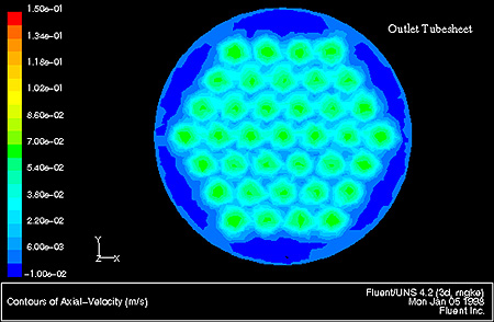
The analysis using the RNG k-e turbulence model showed that as flow passed from the 200-mm nozzle the momentum pressure loss of expanding into the header was greater than the frictional pressure loss across the bundle. Hence the majority of the fluid remained concentrated in a few tubes at the center of the bundle. The velocity in the center of the bundle was more than double that at the periphery leaving about 75% of the surface area ineffective.
Matrix inserts provide answer (back to top)
Cal Gavin engineers then modified the model to investigate the effects of adding wire matrix inserts. These inserts are a proprietary product of Cal Galvin known as HiTran inserts. In this case, the inserts were thought to increase the resistance to flow across each tube and thereby even out the flow distribution in the bundle. At the same time the inserts would create more ideal flow conditions within individual tubes by continuously removing stagnant fluid from the tube wall and replacing it with fluid from the center of the tubes. This reduces the residence time of fluid in contact with the heat transfer surface and creates a flow regime where the velocity profile across the tube is nearly flat.
Although wire matrix inserts depend upon an increase in pressure drop to achieve these flow conditions the enhancement in heat transfer is much larger than would be achieved by simply increasing tubeside velocities. In fact heat transfer enhancement is usually achieved at much lower superficial velocities than would be employed in plain tube designs. Thus it is often possible to reconfigure a bundle to reduce the number of passes and maintain or reduce the original pressure drop while still dramatically increasing the performance of the unit.
Re-analyzing the heat exchanger with the inserts added showed that the flow distribution was now quite even across all of the exchanger. The result was a dramatic improvement in heat transfer efficiency with all the installed area now effective. Based on known data from similar heat exchangers Cal Gavin engineers estimated that the heat transfer of the exchanger would be increased by a factor of nine with the relatively minor cost of installing the wire matrix inserts. This application amply demonstrates how CFD can enable engineers to dramatically improve the performance of heat exchangers and other fluid flow devices. For the first time it allows engineers to take a virtual look inside these devices in order to optimize performance and maximize the return from their capital assets.
For more information:
Fluent Inc., 10 Cavendish Court, Centerra Resource Park, Lebanon, NH 03766
Tel: 603-643-2600
Fax: 603-643-3967
Peter Ellerby is engineering manager at Cal Gavin Ltd., and can be reached at:
Cal Gavin Limited
Station Road Alcester
Warwickshire, UK B49 5ET
Tel: +44 (0)1789 400 401
Fax: +44 (0)1789 400 411